YWCT’s experienced engineering team brings you the highest value solution for any cooling tower application. Every solution is custom designed fresh: We make sure our cooling towers meet all required technical specifications, and do so in the most cost-efficient and easy-to-operate fashion.
Provide you with CAD drawings in 2-D or 3-D models for every project.
Offer you P&ID whenever complexity of the cooling system(s) so requires.
Run computerized thermal ratings and performance tests with your figures including “What If?“ scenarios.
Adjust our solution to existing conditions on site such as existing concrete water basin space constraints and existing equipment (e.g. pumps piping motors) quality and composition.
Our engineering team will work with you closely throughout the process of designing, budgeting, and planning your cooling tower until the right solution is reached.
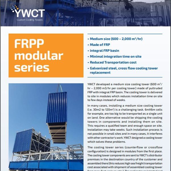
MODULARIZED
ON-SITE-ERECTED COOLING TOWERS
To download, press the button below
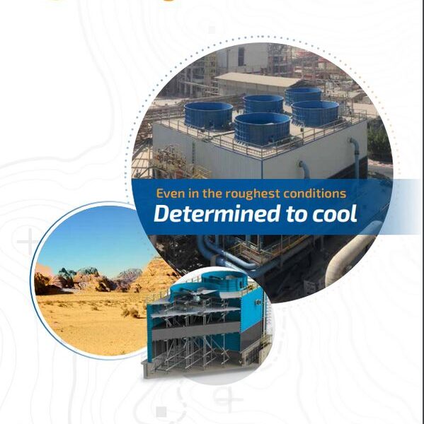
FIELD–ERECTED COOLING TOWERS
To download, press the button below
FRPP: PULTRUDED FRP COUNTERFLOW COOLING TOWERS
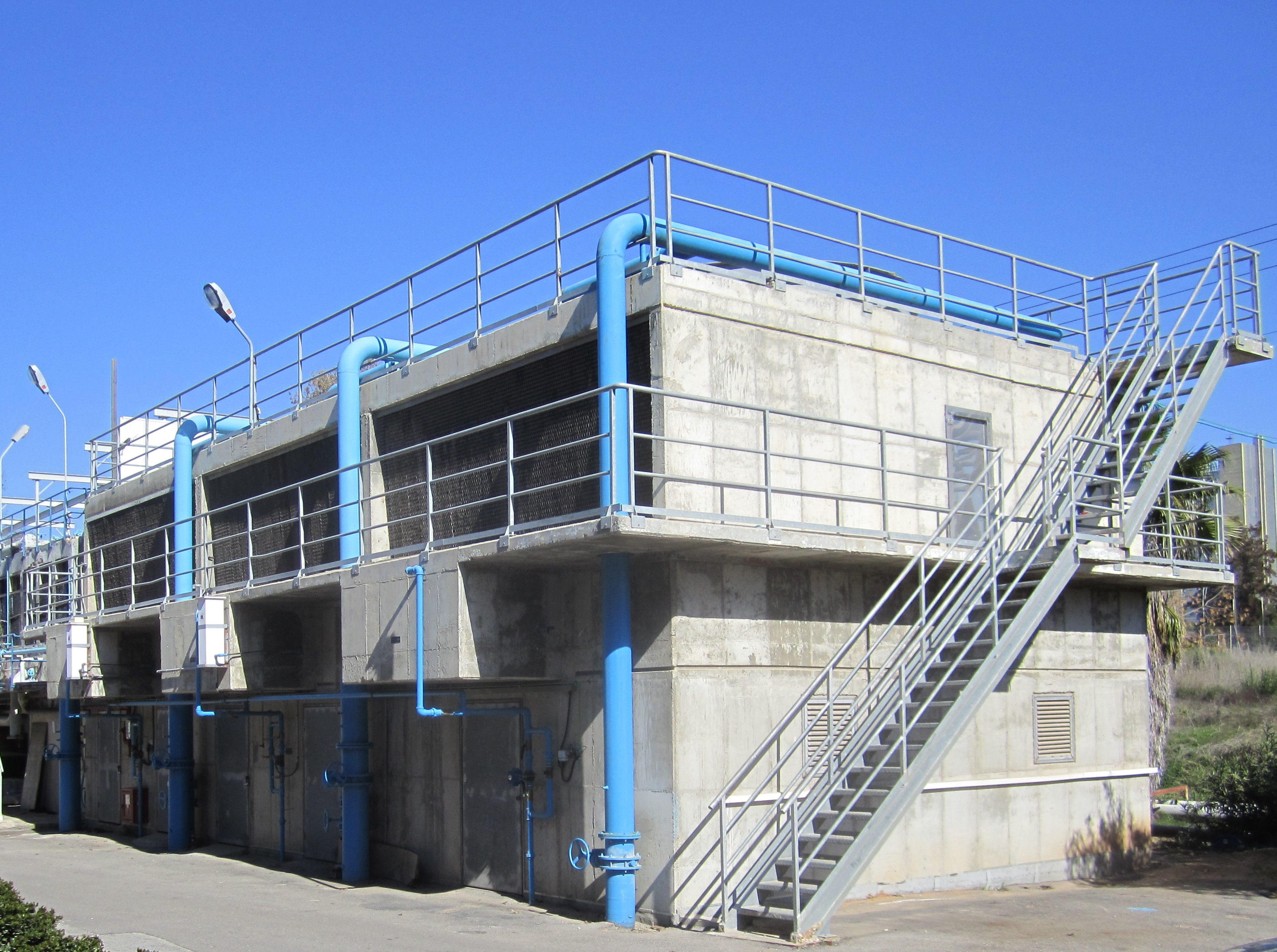
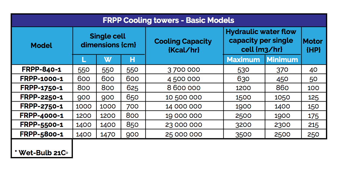
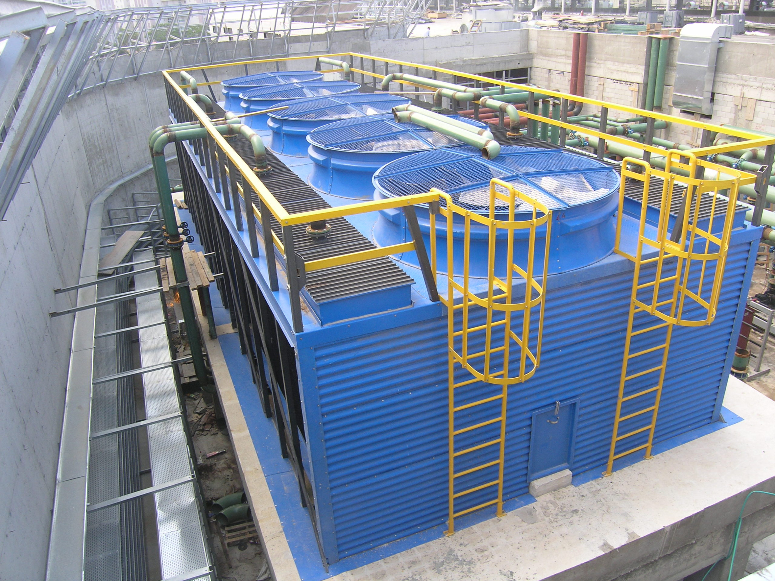
YWCT’s FRPPs are induced-draft cooling towers made of FRP. The structure of our FRPP series (support beams and columns) is made of composite continuous fiberglass pultruded sections that comply with CTI’s STD 37 and conform to ASTM E84D with a flame spread rating of below 25. FRPP cooling towers are positioned over a concrete basin. Just as for our CING series, YWCT provides its customers with scale drawings of the concrete cement, including locations and production drawings of all pipe fittings in 2D or 3D. Also, as in our CING series, the size of a single cell ranges from 6m X 6m to 15m X 15m. When the concrete basin is ready on site, YWCT sends its assembly teams to the job site, where one team sets the pultruded FRP structure, and the other furnishes the cell once the first team has erected it.
Capacity: 2,000,000-20,000,000 kcal/hr per cell
Water flow: 400 – 4,000 m³/hr per cell
FRPPX: PULTRUDED FRP CROSS FLOW COOLING TOWERS
YWCT’s FRPPXs are cross flow fiberglass cooling towers in induced draft appearance made of FRP. The structure of our FRPP series (support beams and columns) is made of composite continuous fiberglass pultruded sections that comply with CTI’s STD 37 and conform to ASTM
E84D with a flame spread rating of below 25. FRPP cooling towers are positioned over a concrete basin. Just as for our CING series, YWCT provides its customers with scale drawings of the concrete cement, including locations and production drawings of all pipe fittings in 2D or 3D. Also, as in our CING series, the size of a single cell ranges from 3m X 6m to 6m X 8m. The cross flow configuration ensures easy maintenance and many years of service.
When the concrete basin is ready on site, YWCT sends its assembly teams to the job site, where one team sets the pultruded FRP structure, and the other furnishes the cell once the first team has erected it.
Pultruded FRP cooling towers have become an alternative solution to traditional concrete cooling towers, since in many cases they cost less and their erection time is much shorter than that of cooling towers made entirely of concrete. In addition, pultruded FRP towers in many cases offer superior corrosion resistance.
Capacity: 1,000,000 – 5,000,000 kcal/hr per cell
Water flow: 200 – 1,000 m³/hr per cell
CING: Concrete Counterflow Cooling Towers
Concrete cement cooling towers designed for heavy industrial applications such as power plants; petrochemical and chemicals plants; and refineries of various kinds. YWCT provides its customers with scale drawings of the concrete cement structure, including locations and production drawings of all pipe fittings in 2D or 3D. The size of a single cell ranges from 6m x 6m to 15m x 15m.
In most cases, our customers (who are familiar with the local market and regulations) choose to take responsibility for the civil engineering and the concrete work. Our engineering department guides the concrete construction process from beginning to completion, ensuring that on-site work meets all requirements. While construction is taking place, all relevant parts of the cooling tower are purchased or manufactured and sent to the job site. When the structure is ready, our assembly team flies to the job site to install and furnish the cooling towers with fill, louvers, fan, motor unit, and fan stack until the cooling tower is operational. Operations are conducted by an experienced team of foremen and laborers, who can be assisted by local labor to reduce costs.
Choosing a concrete structure ensures the end user the longest product life for the cooling tower, and may be the least costly solution for certain customers who already work with a concrete contractor, particularly in locations where labor is less costly.
Capacity: 2,000,000 – 20,000,000 kcal/hr per cell
Water flow: 400 – 4,000 m³/hr per cell
CIRG: CONCRETE CROSSFLOW COOLING TOWERS
Concrete cement cooling towers designed for industrial applications and big HVAC systems. YWCT provides its customers with scale drawings of the concrete cement structure, including locations and production drawings of all pipe fittings in 2D or 3D. The size of a single cell ranges from 6m x 3m to 8m x 6m.
In most cases, our customers (who are familiar with the local market and regulations) choose to take responsibility for the civil engineering and the concrete work. Our engineering department guides the concrete construction process from beginning to completion, ensuring that on-site work meets all requirements. While construction is taking place, all relevant parts of the cooling tower are purchased or manufactured and sent to the job site. When the structure is ready, our assembly team flies to the job site to install and furnish the cooling towers with fill, fan, motor unit, and fan stack until the cooling tower is operational. Operations are conducted by an experienced team of foremen and laborers, who can be assisted by local labor to reduce costs.
Choosing a concrete structure ensures the end user the longest product life for the cooling tower, and may be the least costly solution for certain customers who already work with a concrete contractor, particularly in locations where labor is less costly.
Capacity: 1,000,000 – 5,000,000 kcal/hr per cell
Water flow: 200 – 1,000 m³/hr per cell


![FRPP_foto-k-textu-1024x768[1]](https://cappa-cooling.eu/wp-content/uploads/2020/01/FRPP_foto-k-textu-1024x7681-1.jpg)
![FRPP_image-k-textu[1]](https://cappa-cooling.eu/wp-content/uploads/2020/01/FRPP_image-k-textu1-scaled.jpg)
![CING_foto-k-textu[1]](https://cappa-cooling.eu/wp-content/uploads/2020/01/CING_foto-k-textu1-scaled.jpg)
